


 English
 中文简体
 русский
 Español
 عربى

How to Calculate Cable Size: A Practical Guide for Engineers and Buyers
Content
- 1 Why Correct Cable Sizing Matters
- 2 The Standard Cable Size Calculation Formula
- 3 Step-by-Step Cable Size Calculation Process
- 4 Practical Cable Size Table for Common Low-Voltage Installations
- 5 How Cable Construction and Insulation Type Affect Sizing
- 6 Common Cable Sizing Mistakes to Avoid
- 7 Practical Considerations for Cable Buyers and Project Engineers
- 8 Final Thoughts on Cable Size Calculation
Choosing the right cable size is one of the most important decisions in any electrical installation. Too small, and the cable overheats; too large, and you waste material and money. For engineers, contractors, and procurement professionals, understanding how to calculate cable size correctly ensures safe, efficient, and code-compliant power delivery. This guide walks through the key factors, formulas, and practical steps used in cable sizing, with the working principles that cable manufacturers like Wuxi Guanghuan Cable apply to real-world projects.
Why Correct Cable Sizing Matters
Cable sizing is not just about matching a conductor to a load. It directly affects safety, operational continuity, and project cost. An undersized cable can overheat under load, damaging insulation and creating fire hazards. An oversized cable increases material cost and may require larger conduits and supports. Correct sizing balances thermal capacity, voltage drop, short-circuit withstand, and installation conditions.
When calculating cable size, four core factors must be considered:
- Current-carrying capacity (ampacity): the maximum current a cable can carry continuously without exceeding its insulation temperature rating.
- Voltage drop: the reduction in voltage along the cable length, which must stay within acceptable limits for the connected equipment.
- Short-circuit rating: the cable's ability to withstand fault current until protection devices operate.
- Installation conditions: ambient temperature, grouping, burial depth, conduit type, and altitude all affect heat dissipation.
The Standard Cable Size Calculation Formula
In most low-voltage applications, the starting point for cable sizing is the design current. The basic formula for single-phase and three-phase systems is:
Single-phase: I = P / (V × cos φ)
Three-phase: I = P / (√3 × V × cos φ)
Where:
- I = design current in amperes (A)
- P = connected load in watts (W)
- V = line voltage in volts (V)
- cos φ = power factor (typically 0.8 to 0.95)
Once you know the design current, you can select a candidate conductor size from a current-carrying capacity table, then apply correction factors for ambient temperature, grouping, and installation method. The corrected ampacity must be equal to or greater than the design current.
Voltage Drop Calculation
Voltage drop is often the limiting factor on long cable runs. The voltage drop formula for a three-phase system is:
Voltage drop (V) = (√3 × I × L × (R cos φ + X sin φ)) / 1000
For single-phase systems, replace √3 with 2. In most practical low-voltage cable sizing, the reactive component X is small and may be neglected for cross-sections up to a certain size. The acceptable voltage drop is usually specified by national standards or project specifications, commonly 3% to 5% for lighting and power circuits.
Short-Circuit Consideration
A cable must also withstand the thermal effect of a short circuit until the protective device clears the fault. The minimum conductor cross-sectional area can be estimated using the adiabatic equation:
S = (I² t) / k
Where S is the minimum cross-sectional area in mm², I is the fault current in amperes, t is the disconnection time in seconds, and k is a constant depending on conductor and insulation material. This check ensures that the cable does not melt or damage its insulation during a fault event.
Step-by-Step Cable Size Calculation Process
For a practical calculation, follow these steps:
- Determine the total connected load and calculate the design current using the appropriate power formula.
- Identify the installation method: clipped direct, in conduit, buried directly, or in cable tray, since each affects heat dissipation.
- Apply correction factors for ambient temperature and grouping. For example, cables installed together in a bundle need a derating factor.
- Select a provisional cable size from the manufacturer's ampacity table where the corrected current rating meets or exceeds the design current.
- Check voltage drop over the cable route length. If the voltage drop exceeds the acceptable limit, increase the cross-section.
- Verify the cable withstands the prospective short-circuit current.
- Review mechanical strength and any special requirements such as flexibility, fire resistance, or UV protection.
Practical Cable Size Table for Common Low-Voltage Installations
The table below shows typical current-carrying capacities for copper and aluminum cables in common low-voltage power distribution applications. Values are indicative only; always refer to the manufacturer's technical data for a specific cable construction.
| Conductor cross-section (mm²) | Copper, PVC insulated (A) | Copper, XLPE insulated (A) | Aluminum, XLPE insulated (A) |
|---|---|---|---|
| 1.5 | 17.5 | 22 | — |
| 2.5 | 24 | 30 | — |
| 4 | 32 | 40 | 31 |
| 6 | 41 | 51 | 39 |
| 10 | 57 | 70 | 53 |
| 16 | 76 | 94 | 71 |
| 25 | 101 | 119 | 93 |
| 35 | 125 | 148 | 115 |
| 50 | 151 | 182 | 139 |
| 70 | 192 | 232 | 178 |
| 95 | 232 | 282 | 216 |
| 120 | 269 | 328 | 251 |
| 150 | 309 | 379 | 290 |
| 185 | 353 | 434 | 333 |
| 240 | 415 | 514 | 392 |
| 300 | 477 | 593 | 452 |
For longer cable routes, voltage drop often determines the final cross-section. A 16 mm² copper cable may carry 94 A thermally, but on a 200-meter run at 400 V three-phase, the voltage drop may exceed the acceptable limit, requiring a 25 mm² or 35 mm² cable.
How Cable Construction and Insulation Type Affect Sizing
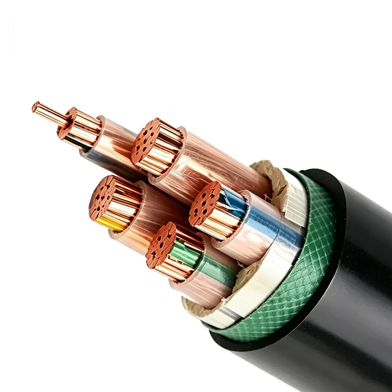
The insulation material directly influences the maximum operating temperature and therefore the ampacity. PVC-insulated cables typically have a maximum conductor temperature of 70°C, while XLPE-insulated cables can operate at 90°C continuous. This means an XLPE cable such as 6/1kV XLPE insulated power cable can carry more current than a PVC-insulated cable of the same cross-section, making it a common choice for higher-load distribution and industrial feeders.
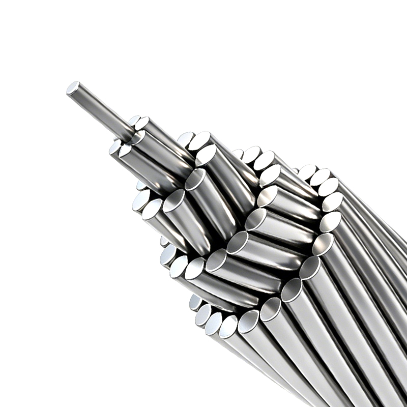
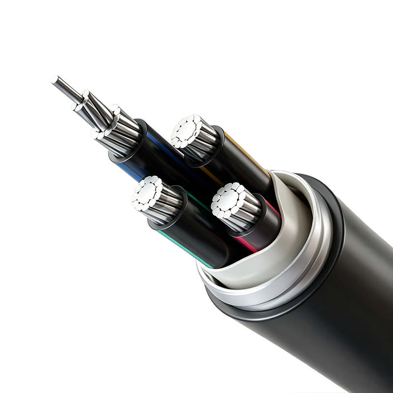
Conductor material also matters. Copper has higher conductivity than aluminum, so for the same current, an aluminum conductor needs a larger cross-section. Aluminum conductors are lighter and often more economical for large feeders, as seen in AAC, AAAC, and ACSR overhead conductors. For underground low-voltage distribution, aluminum alloy conductor cables offer a cost-effective alternative while maintaining reliable connections.
In addition, special application requirements can influence cable selection. For example, in installations that require fire safety, a flame-retardant and fire-resistant cable design is preferred. And for long industrial drive connections, a variable-frequency drive cable is designed to reduce harmonic interference and withstand voltage spikes.
Common Cable Sizing Mistakes to Avoid
Even experienced engineers sometimes make sizing errors. The most common mistakes include:
- Ignoring ambient temperature correction factors, especially in hot environments such as cable trays near roofs or in industrial plants.
- Overlooking grouping derating when multiple cables run close together, causing mutual heating.
- Forgetting to check voltage drop for long runs, leading to equipment underperformance.
- Selecting a cable based only on full-load current while ignoring starting current or transient overloads.
- Not accounting for future load growth, which often leads to premature replacement.
A reliable approach is to add a margin of 10% to 20% to the calculated design current, depending on the project's expansion plans. This practice is common in both industrial and infrastructure projects.
Practical Considerations for Cable Buyers and Project Engineers
When you receive a cable specification, it is wise to verify the sizing assumptions before placing an order. Ask about the installation method, ambient temperature, maximum allowable voltage drop, and fault level. A responsible cable supplier will help you confirm the technical parameters and recommend the correct product series.
At Wuxi Guanghuan Cable, we manufacture a wide range of power cables from low-voltage to 35 kV, including both PVC insulated and XLPE insulated power cables. Our production lines cover aluminum and copper conductors, armored and unarmored constructions, and flame-retardant or fire-resistant derivatives. We also provide guidance on cable selection through our technical documentation and after-sales service.
For projects involving underground distribution in residential or industrial zones, our aluminum alloy conductor plastic insulated power cable offers a balanced combination of economy and reliability. Whatever cable size calculation method you use, the key is to document your assumptions and verify the final design against the actual installation environment.
Final Thoughts on Cable Size Calculation
Calculating cable size is a systematic process that balances thermal, electrical, and mechanical limits. Start with the design current, apply correction factors, check voltage drop, and verify short-circuit withstand capability. Use manufacturer data tables rather than generic memory values, because the actual current rating depends on the precise cable construction and insulation system.
If you are working on a medium-voltage distribution project, a 26/35 kV XLPE cable introduces additional considerations such as partial discharge performance and sheath earthing, so the sizing process should be reviewed by an experienced electrical engineer. For standard low-voltage installations, the steps in this article give you a reliable foundation.
For more insight into selecting the right cable for your specific application, read our guide on key factors to consider when choosing power cables. Understanding these fundamentals helps you make informed decisions, avoid costly mistakes, and ensure safe long-term operation.
-
AAC, AAAC & ACSR - Aluminum and Aluminum Alloy Stranded Conductors
-
Aluminum Alloy Conductor Plastic Insulated Power Cable (Rated Voltage up to 26/35kV)
-
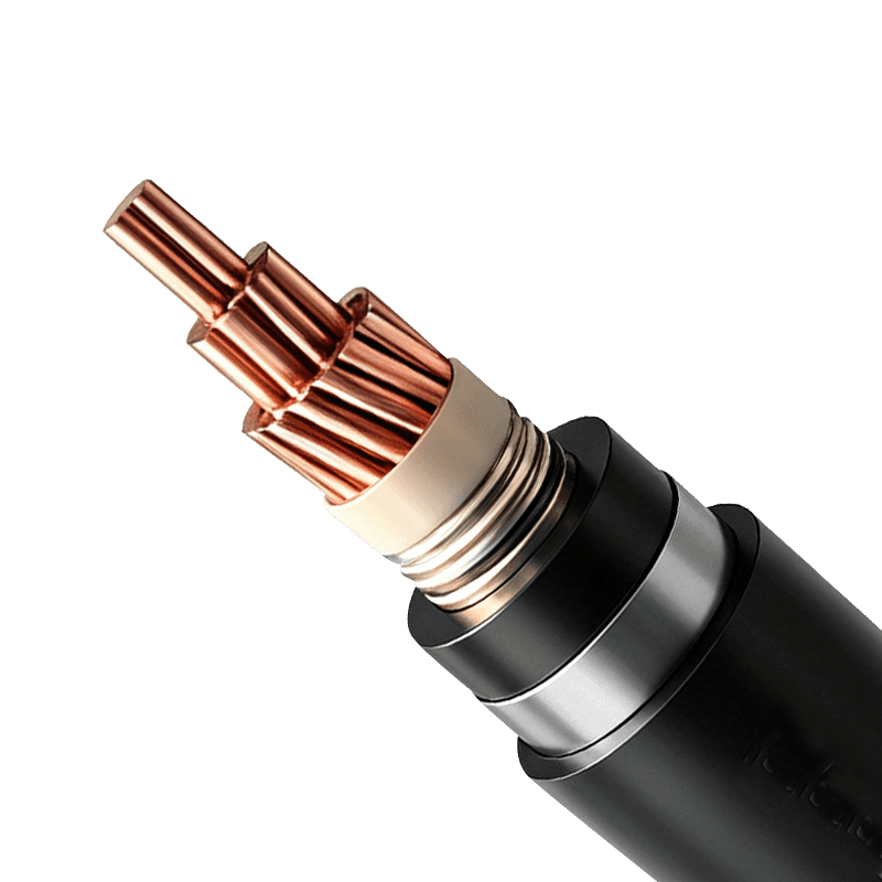
Power Cable for Subway and Urban Rail Transit (Rated Voltage 35kV)
-
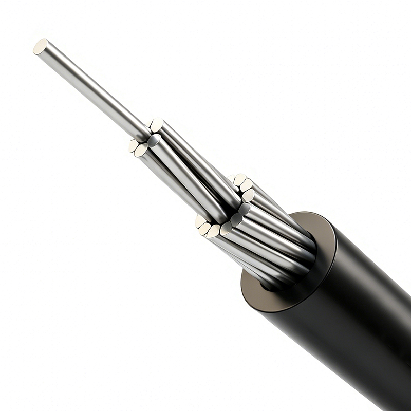
Aerial Insulated Cable (Rated Voltage 1kV, 10kV, 20kV, 35kV)
-
Termite and Rodent Resistant Cable

Copyright © Wuxi Guanghuan Cable Co., Ltd. All Rights Reserved. Power Cables Manufacturer Electrical Wire And Cable Factory

