


 English
 中文简体
 русский
 Español
 عربى

How to Calculate Cable Size: A Step-by-Step Guide for Electrical Projects
Content
- 1 Before You Start: Collect the Inputs
- 2 Step 1 - Calculate the Design Current (Ib)
- 3 Step 2 - Coordinate the Cable with the Protective Device
- 4 Step 3 - Find the Base Current-Carrying Capacity
- 5 Step 4 - Apply the Correction Factors
- 6 Step 5 - Check the Voltage Drop
- 7 Step 6 - Verify Short-Circuit Withstand
- 8 A Worked Example
- 9 Where Cable Sizing Usually Goes Wrong
- 10 Two Cases That Need Extra Care
- 11 From Calculation to a Cable You Can Trust
Ask any experienced electrical engineer and you will hear the same thing: cable sizing is not one formula but a short chain of checks, and every link in that chain has to hold. Get the current right but ignore the derating factors, and the conductor runs hotter than its insulation was ever designed for. Get the ampacity right but ignore voltage drop, and the motor at the far end of the line refuses to start. Skip the short-circuit check, and the installation sits one fault away from a serious incident.
The method below follows the sequence our own engineers use when they review a project: design current first, then coordination with the protective device, then current-carrying capacity, then voltage drop, then short-circuit withstand. Work through the steps in order and the correct cross-section will almost choose itself.
Before You Start: Collect the Inputs
Almost every delay in a cable sizing exercise traces back to a missing input. Gather these before you open a table:
- Load data: power in kW or kVA, power factor, efficiency, duty cycle and simultaneity.
- System data: nominal voltage, number of phases, frequency, and whether the supply is TN, TT or IT.
- Protection data: type and rating of the circuit breaker or fuse, and its tripping characteristics.
- Installation method: multicore or single-core, on a tray, in conduit, clipped direct, in free air, or buried.
- Environment: ambient air temperature, soil temperature and thermal resistivity, burial depth, and how many circuits share the route.
- Route data: one-way length in metres, plus any future extension already planned.
- Fault data: prospective short-circuit current at the origin and the required disconnection time.
Write the values down. A sizing sheet that shows its inputs can be reviewed in minutes; one that does not will always be questioned.
Step 1 - Calculate the Design Current (Ib)
The design current is the current the cable will carry in normal service. For a three-phase load:
Ib = P / (√3 × U × cos φ)
and for a single-phase load:
Ib = P / (U × cos φ)
A quick illustration: a 90 kW three-phase load on a 400 V supply at 0.85 power factor draws 90,000 / (1.732 × 400 × 0.85) = 153 A. That single number sets the floor for everything that follows, because the protective device must be at least this large and the cable must be at least this capable.
Two refinements are worth remembering. Motor starting current does not change the continuous design current, but it does affect the choice of protection and the voltage drop check. And in installations with a high harmonic content, such as offices full of electronic loads or a plant full of drives, the neutral conductor may need to be sized for more than the phase current rather than less.
Step 2 - Coordinate the Cable with the Protective Device
A cable is only protected if the device in front of it disconnects before the insulation is damaged. In practice that means two conditions have to be satisfied at the same time:
Ib ≤ In ≤ Iz
where Ib is the design current, In is the nominal rating of the protective device, and Iz is the corrected current-carrying capacity of the cable. A second condition, I2 ≤ 1.45 × Iz, confirms that the device will actually operate at its conventional tripping current without overheating the conductor.
The practical consequence is simple. If the calculated current is 153 A, you do not choose a 200 A breaker and then hunt for a cable big enough to match it; you choose the smallest standard rating above the load, which is 160 A here, and size the cable against that figure.
Step 3 - Find the Base Current-Carrying Capacity
Tables of current-carrying capacity, whether taken from IEC 60364-5-52, BS 7671 or a manufacturer's catalogue, are built around a defined set of conditions: a reference ambient temperature, a stated installation method, a defined number of loaded conductors and a single circuit. Find the row that matches your cross-section and the column that matches your installation.
Three choices dominate the result. The conductor material matters, because aluminium needs roughly one and a half times the cross-section of copper for the same current. The insulation matters, because an XLPE cable may run with a conductor at 90 °C while a PVC cable is limited to 70 °C. And the installation method matters enormously, since a cable clipped in free air sheds heat far more easily than the same cable pulled into a crowded conduit.
This is where a real catalogue becomes genuinely useful, because the gap between insulation types is not a rounding error. A 6/1 kV XLPE insulated power cable carries noticeably more current than a PVC equivalent of the same copper cross-section, simply because its insulation tolerates a higher conductor temperature.
 Rated Voltage 0.6/1kV XLPE Insulated Power CableThe rated voltage 0.6/1kV cross-linked polyethylene insulated power cable adopts chemical or physical methods to transform polyethylene molecules from a linear structu...View Product →
Step 4 - Apply the Correction Factors
Real installations never match the reference conditions of a table, so the base capacity has to be reduced. The factors multiply together:
Iz = It × Ca × Cg × Cs × Cd
| Factor | Symbol | What it depends on | Typical range |
|---|---|---|---|
| Ambient temperature | Ca | Air or soil temperature above the reference | 0.71 - 1.00 |
| Grouping | Cg | Number of circuits and how they are spaced | 0.70 - 1.00 |
| Soil thermal resistivity | Cs | Backfill material and native soil | 0.75 - 1.15 |
| Depth of laying | Cd | Burial depth and surface conditions | 0.90 - 1.05 |
| Thermal insulation | Ci | Cable surrounded by insulation | 0.50 - 0.90 |
If the derated capacity comes out below the rating of the protective device, move up one cross-section and repeat the calculation. It is common for a cable to pass the current check only after two or three attempts.
Step 5 - Check the Voltage Drop
A cable that carries the current may still be too small for the route. Voltage drop rises with both current and length, and it is the check that most often forces a larger cross-section on long feeders.
Voltage drop = (mV/A/m × Ib × L) / 1000
For a three-phase circuit the tabulated mV/A/m value already includes the factor of √3. Typical limits are 3 % for lighting circuits and 5 % for power circuits, measured from the origin of the installation to the terminals of the load, with the allowance shared between the feeder and the final circuit.
Take a 70 mm² copper conductor carrying 160 A over 80 m. Its three-phase drop is about 0.58 mV/A/m, so the loss is 0.58 × 160 × 80 / 1000 = 7.4 V, or 1.9 % of 400 V, which is comfortably inside the limit. Had the route been 300 m instead, the same calculation would have produced 27.8 V and forced a step up in cross-section.
Step 6 - Verify Short-Circuit Withstand
During a fault the conductor carries a current many times its normal rating, and it has to survive long enough for the protection to clear the fault. The adiabatic check is the standard approach:
S ≥ (I × √t) / k
Here I is the prospective fault current in amperes, t is the disconnection time in seconds, and k is a constant that depends on the conductor material and its insulation. For copper conductors, k is typically 143 with XLPE insulation and 115 with PVC, while aluminium conductors use lower values. A 20 kA fault cleared in 0.2 s requires 20,000 × 0.447 / 143 = 62.5 mm² of copper, which is why the short-circuit check, rather than the current check, sometimes decides the final size.
The protective conductor deserves the same attention. It must withstand the same fault energy, and it must be sized so that the earth fault loop impedance allows the device to trip within the permitted time.
A Worked Example
Put the six steps together for a 90 kW motor feeder on a 400 V system at 0.85 power factor, routed 80 m on a tray in 40 °C air with two other loaded circuits beside it.
| Step | Check | Result |
|---|---|---|
| Design current | 90,000 / (1.732 × 400 × 0.85) | 153 A |
| Protective device | Smallest standard rating above 153 A | 160 A |
| Base capacity | 70 mm² copper XLPE, on tray | 229 A |
| Derated capacity | 229 × 0.91 × 0.85 | 177 A |
| Voltage drop | 0.58 × 160 × 80 / 1000 | 7.4 V (1.9 %) |
| Short-circuit | 20 kA for 0.2 s, k = 143 | 62.5 mm² required |
| Selected cable | Largest requirement with margin | 3 × 70 mm² + 35 mm² PE |
The answer is a four-core 70 mm² copper XLPE cable. Note which step set the size: 70 mm² was needed to carry 160 A after derating, and it also happens to satisfy the adiabatic check with only a small margin. Reduce the grouping or the ambient temperature and that margin disappears.
Where Cable Sizing Usually Goes Wrong
- Sizing on the nominal load while ignoring diversity, spare capacity or future expansion.
- Using a table based on 30 °C when the plant room runs at 45 °C.
- Ignoring grouping, even though three circuits on one tray derate a cable far more than most people expect.
- Reading a PVC column for an XLPE cable, or the reverse.
- Checking voltage drop at the first load on the circuit instead of the last.
- Forgetting that the neutral can carry harmonic currents in three-phase four-wire circuits.
- Treating the short-circuit check as optional on short runs, where it is often the deciding factor.
Two Cases That Need Extra Care
Medium-voltage feeders
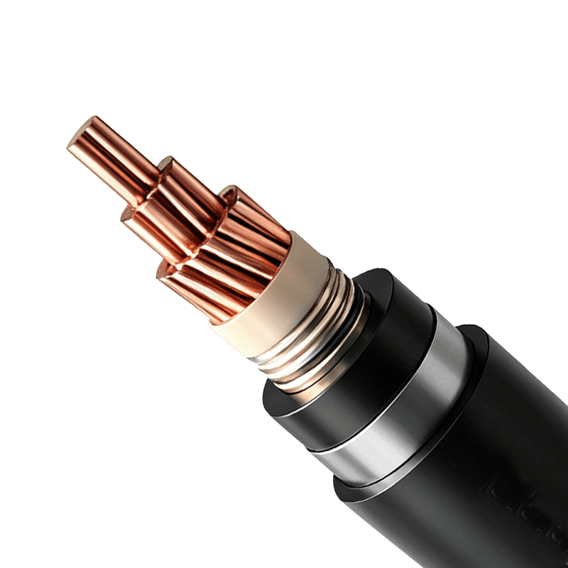
From 3.6/6 kV up to 26/35 kV the logic stays the same, but insulation thickness, screen construction and the earthing of the metallic sheath join the calculation. The metallic screen has its own short-circuit duty to satisfy, and the earthing arrangement affects both the fault level and the thermal behaviour of the cable. Sizing a 26/35 kV XLPE insulated power cable therefore means checking the same limits with an additional set of screen and earthing conditions attached.
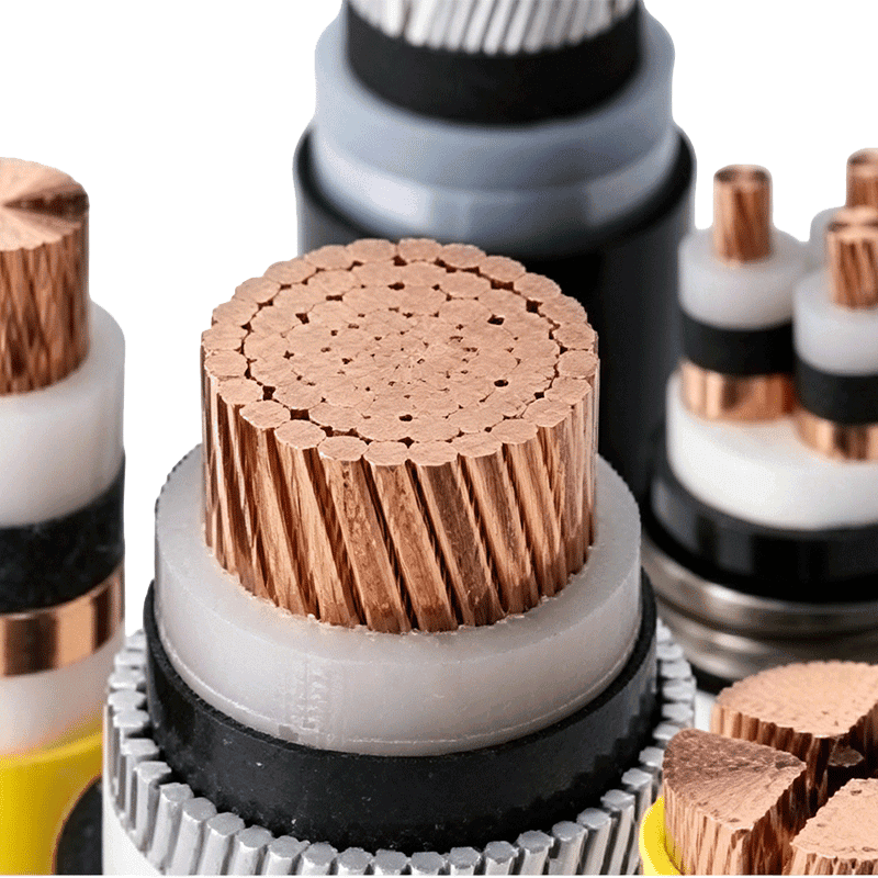 Rated Voltage 3.6/6kV–26/35kV XLPE Insulated Power CableThe rated voltage 3.6/6kV–26/35kV cross-linked polyethylene insulated power cable adopts an advanced cross-linking process. Through chemical or physical methods, polye...View Product →
Variable-frequency drive circuits
Drives push harmonic currents and fast voltage pulses through the cable, so the current you calculate from the motor nameplate is not the current the cable actually sees. A dedicated drive cable with a symmetrical three-core construction and a properly bonded screen keeps those currents under control and reduces electromagnetic interference on neighbouring circuits. Where long motor leads are involved, the drive manufacturer's cable length limits should be treated as part of the sizing exercise.
 Variable Frequency Drive Cable (Rated Voltage up to 6kV)Product Overview Frequency transformer cables (commonly known as VFD cables) are power transmission lines specifically engineered for industrial variable frequency con...View Product →
From Calculation to a Cable You Can Trust
The arithmetic is not difficult. The difficulty lies in the numbers you feed into it, meaning the ambient temperature, the grouping, the fault level and the route length, and in knowing which standard governs the project.
Wuxi Guanghuan Cable Co., Ltd. has been manufacturing cables in Guanlin, Yixing since 1998, across more than 100 product varieties and roughly 30,000 specifications, from 450/750 V wiring to 26/35 kV XLPE power cables, with quality management certified to ISO 9001 and products approved by TUV Rheinland. Every order starts with a sizing conversation, because the most economical cable is the one that is right the first time. Send us the load, the route and the environment, and our engineers will return a sized recommendation with the derating factors shown in full. A quick look at our factory shows how those cables are produced, tested and prepared for delivery.
If you would like to go one level deeper into how product performance interacts with sizing, our article on the key factors to consider when choosing power cables is a useful companion to this guide.
-
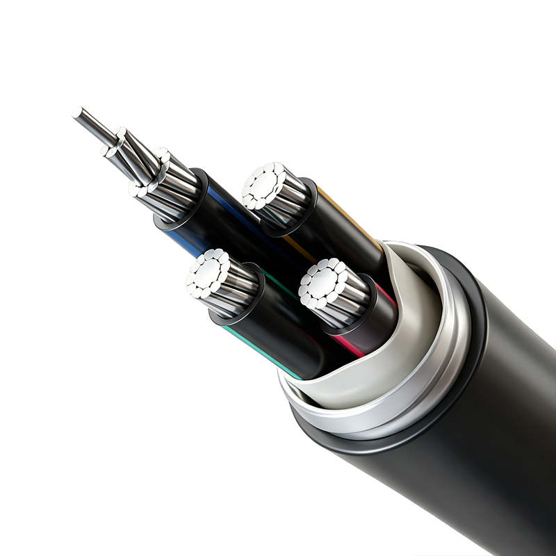
Aluminum Alloy Conductor Plastic Insulated Power Cable (Rated Voltage up to 26/35kV)
-
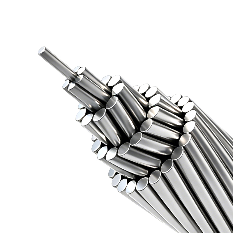
AAC, AAAC & ACSR - Aluminum and Aluminum Alloy Stranded Conductors
-
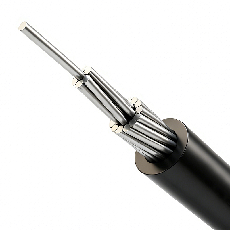
Aerial Insulated Cable (Rated Voltage 1kV, 10kV, 20kV, 35kV)
-
Power Cable for Subway and Urban Rail Transit (Rated Voltage 35kV)
-
Variable Frequency Drive Cable (Rated Voltage up to 6kV)


Copyright © Wuxi Guanghuan Cable Co., Ltd. All Rights Reserved. Power Cables Manufacturer Electrical Wire And Cable Factory

