


 English
 中文简体
 русский
 Español
 عربى

How to Calculate Cable Size: A Step-by-Step Guide for Safe, Real Projects
Content
- 1 What a Correct Cable Size Really Means
- 2 Step 1: Establish the Design Current
- 3 Step 2: Apply Derating Factors for Real Conditions
- 4 Step 3: Check Voltage Drop Along the Run
- 5 Step 4: Verify Short-Circuit Withstand
- 6 Putting It All Together
- 7 From the Calculation to the Cable You Actually Order
- 8 Sizing for Solar, VFD and Other Special Loads
- 9 Common Sizing Mistakes We See in Tender Documents
- 10 Run the Numbers With a Manufacturer Who Does This Daily
Getting the conductor size right is one of those decisions that quietly determines whether an installation runs comfortably for thirty years or overheats in its first hot summer. An undersized cable wastes energy, shortens insulation life and creates a genuine fire risk; a cable two sizes too large ties up money in copper the circuit never needed. Learning how to calculate cable size is really about balancing four different checks against each other.
This guide follows the same sequence our engineers use when a customer sends in a load schedule: find the design current, correct it for the way the cable is actually installed, confirm the voltage drop over the full run length, and verify that the conductor survives a short circuit.
What a Correct Cable Size Really Means
A conductor is correctly sized only when all four conditions below are satisfied at the same time. If one of them fails, move up to the next standard cross-section and repeat the calculation. Skipping a check is the most common reason a cable sizes perfectly on paper and then fails on site.
| Check | Question it answers | Typical requirement |
|---|---|---|
| Current-carrying capacity | Will the conductor stay inside its temperature rating at full load? | Derated capacity above design current |
| Voltage drop | Will the load still receive adequate voltage at the far end? | 3 to 5 percent of nominal |
| Short-circuit withstand | Can the conductor survive a fault until the breaker clears it? | Adiabatic check |
| Mechanical and installation limits | Is the cross-section large enough to install, bend and terminate? | Minimum per standard |
Step 1: Establish the Design Current
Everything begins with the continuous current the cable has to carry, usually written as Ib. For a three-phase load the relationship is:
Ib = P / (1.732 × U × PF)
For a single-phase or DC circuit, simply drop the 1.732:
Ib = P / (U × PF)
Take a 55 kW three-phase motor on a 400 V supply with a power factor of 0.86. Then Ib = 55,000 / (1.732 × 400 × 0.86), which comes to roughly 92 A. Use the real power factor rather than assuming unity, because the difference between 0.86 and 1.0 is about 16 percent of current and is often exactly the margin that decides a voltage drop check. If the load is a motor, look at starting current too, since the protective device has to ride through the start without tripping.
Design current is not the breaker rating
Once Ib is known, choose a protective device whose rating is at least Ib, then confirm that the derated cable capacity is at least the device rating. Working in that order keeps the conductor both protected and thermally comfortable.
Step 2: Apply Derating Factors for Real Conditions
Catalogue current ratings assume a reference set of conditions, usually one circuit in free air at 30 °C or one circuit buried in soil at 20 °C. Real installations rarely match those assumptions, so every deviation is handled with a correction factor and the factors multiply:
Iz = It × k1 × k2 × k3 ...
where It is the tabulated rating and Iz is the capacity actually available. A group of three loaded circuits in one duct on a 40 °C day can lose a third of the nominal rating before voltage drop is even considered.
| Condition | Typical factor | Why it matters |
|---|---|---|
| Ambient air at 40 °C instead of 30 °C | 0.87 to 0.91 | Less temperature headroom |
| Soil at 30 °C instead of 20 °C | 0.89 to 0.94 | Reduced heat dissipation |
| Three loaded circuits grouped in one duct | 0.70 to 0.80 | Mutual heating |
| Burial depth greater than 0.8 m | 0.95 to 0.98 | Thermal resistance of the soil |
| Direct sunlight exposure | 0.80 to 0.90 | Radiant heat gain |
As an example, a factor of 0.87 for a 40 °C ambient multiplied by 0.75 for grouping gives 0.65, so a cable tabulated at 130 A is only good for about 85 A in that arrangement. Never add correction factors together; always multiply them.
Step 3: Check Voltage Drop Along the Run
Voltage drop is the check that most often forces a larger conductor on long feeders, and it cannot be judged from a current table alone. For the resistive part of the circuit:
Vd = k × I × L × R / 1000
where k is 2 for single-phase and DC circuits and 1.732 for three-phase, I is the load current in amperes, L is the one-way route length in metres, and R is the conductor resistance in ohms per kilometre. The percentage drop is then Vd divided by the nominal voltage, multiplied by 100. Most low voltage installations work to 3 percent at the final circuit and 5 percent overall.
In our example, an 80 m run at 92 A on a 50 mm² copper conductor with a resistance of about 0.387 ohms per kilometre gives Vd = 1.732 × 92 × 80 × 0.387 / 1000, which is roughly 4.9 V, or 1.2 percent of 400 V. That passes comfortably. On a 300 m run the same calculation would fail and push the cross-section up several steps, which is exactly why route length belongs in the calculation from the beginning.
Step 4: Verify Short-Circuit Withstand
A cable also has to survive the fault current for as long as it takes the protective device to clear it. The adiabatic equation handles this in one line:
S = square root of (I² × t) / k
where S is the minimum cross-section in mm², I is the prospective fault current in amperes, t is the disconnection time in seconds, and k is a constant for the conductor and insulation combination. Typical values are around 143 for copper with XLPE insulation, 115 for copper with PVC, and 94 for aluminium with XLPE.
A 6 kA fault cleared in 0.1 s in a copper XLPE cable requires the square root of (6000² × 0.1) divided by 143, which is about 13 mm². Our 50 mm² conductor is comfortable. Notice how strongly t matters: the same fault cleared in one second would demand roughly 42 mm², which is why protection settings and cable sizing belong in the same conversation.
Putting It All Together
Here is the complete sequence for the 55 kW motor on an 80 m run, with figures rounded for clarity.
- Design current: 92 A at 400 V with a power factor of 0.86. Protective device rated 100 A.
- Installation conditions: XLPE copper cable on a tray with two other loaded circuits, 40 °C ambient. Combined derating factor 0.65.
- First trial at 35 mm²: tabulated capacity about 130 A, derated to roughly 85 A. Fails, because 85 A is below the 100 A device rating.
- Second trial at 50 mm²: derated capacity about 100 A. Meets the device rating.
- Voltage drop at 50 mm² over 80 m: 4.9 V, or 1.2 percent. Passes.
- Short-circuit requirement: 13 mm² minimum for a 6 kA fault cleared in 0.1 s. Passes.
- Result: 0.6/1 kV XLPE insulated copper cable, four cores at 50 mm², with protection set to clear a fault within 0.1 s.
From the Calculation to the Cable You Actually Order
A cross-section is only part of the specification. Insulation type changes how much current a conductor can carry, because XLPE insulated cables operate at higher conductor temperatures than PVC equivalents and therefore need a smaller cross-section for the same load. We compare the two constructions in more detail in this article on XLPE and PVC insulated power cable performance. Conductor material matters as well: aluminium and aluminium alloy conductors are lighter and more economical, but need a larger cross-section for the same current.
 Rated Voltage 0.6/1kV XLPE Insulated Power CableThe rated voltage 0.6/1kV cross-linked polyethylene insulated power cable adopts chemical or physical methods to transform polyethylene molecules from a linear structu...View Product →
For the majority of low voltage distribution work, 0.6/1 kV XLPE insulated power cable in copper or aluminium covers the range, and the calculation above applies directly. At medium voltage the method is unchanged, but the derating tables, fault levels and insulation thickness requirements are different, so feeders from 3.6/6 kV up to 26/35 kV are usually sized against the utility's own network data.
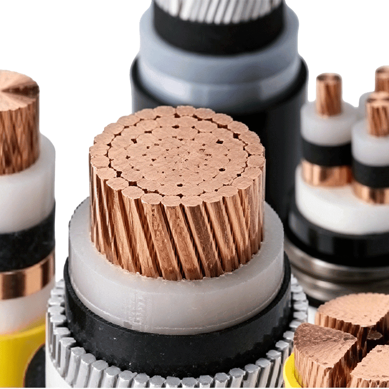 Rated Voltage 3.6/6kV–26/35kV XLPE Insulated Power CableThe rated voltage 3.6/6kV–26/35kV cross-linked polyethylene insulated power cable adopts an advanced cross-linking process. Through chemical or physical methods, polye...View Product →
Sizing for Solar, VFD and Other Special Loads
Some circuits need a modified version of the same procedure. Solar DC strings carry continuous current at high ambient temperature on a rooftop, so the derating factor is applied to a cable that is already warm, and voltage drop is often held to 1 or 2 percent because inverter efficiency suffers at both ends of its input window. Variable frequency drive circuits add harmonic content and pulsed voltage, so screened cable and a check on the rated voltage to earth both become part of the sizing exercise.
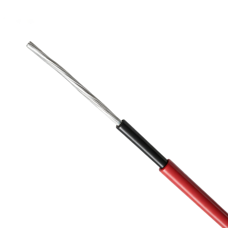 Photovoltaic Cable (PV Cable)Product Overview Photovoltaic cable is a critical component used for DC side transmission within solar PV power generation systems. Specifically engineered for the rig...View Product →
Fire-resistant, termite-resistant and rail transit cables follow the same arithmetic, but the applicable standard adds constraints such as circuit integrity under fire that no calculation can replace.
Common Sizing Mistakes We See in Tender Documents
- Applying one derating factor and forgetting the rest, when grouping, ambient temperature and soil conditions all act at once.
- Using 20 °C resistance values for a conductor that will operate at 70 °C or 90 °C.
- Sizing to a breaker that was already specified rather than to the actual load.
- Ignoring the neutral on circuits with harmonic-rich loads such as office IT equipment or LED lighting.
- Assuming a larger cable fixes a voltage drop problem when the real issue is route length or poor power factor.
- Forgetting the minimum cross-section required for mechanical strength and protective conductor continuity.
Run the Numbers With a Manufacturer Who Does This Daily
Wuxi Guanghuan Cable has been manufacturing wire and cable in Guanlin, Yixing, the area known as China's cable town, since 1998. Our range covers low and medium voltage power cables, overhead conductors, electrical equipment cables and special cables for photovoltaic, rail transit and fire-resistant applications, with more than 100 series and 30,000 specifications produced across 70-plus production and testing lines. The details of our approvals, including TUV Rheinland certification and ISO 9001, ISO 14001, ISO 45001 and ISO 50001 system certificates, are listed on our product certification page.
Send us the load schedule, route length, installation method and ambient conditions, and our engineers will run the same four checks described above and come back with a cross-section, an insulation type and a cable construction that will pass inspection the first time.
-
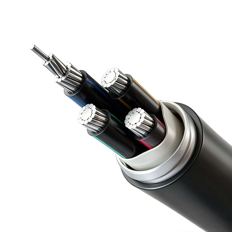
Aluminum Alloy Conductor Plastic Insulated Power Cable (Rated Voltage up to 26/35kV)
-
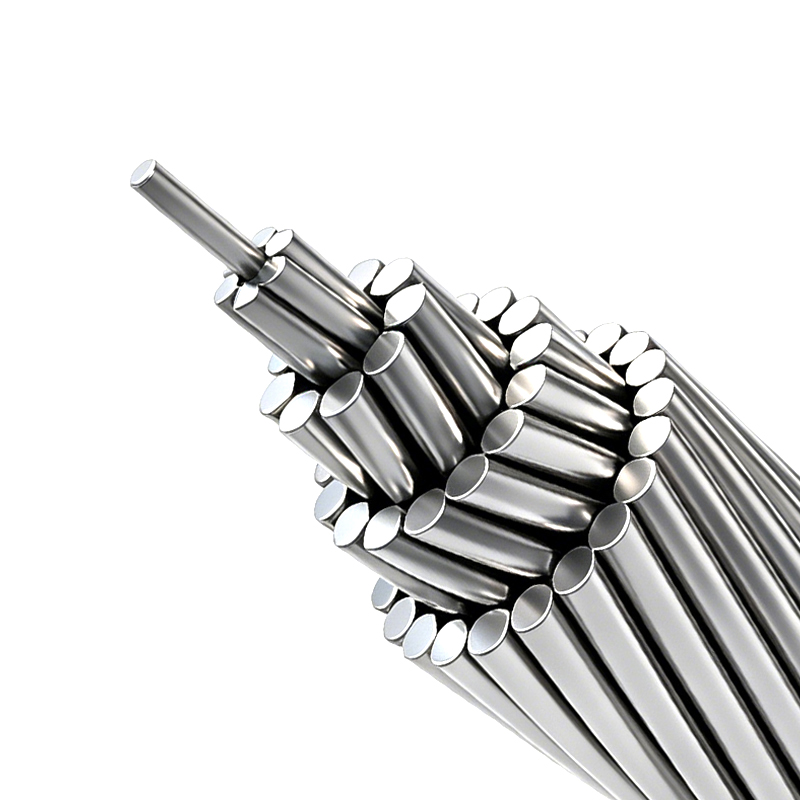
AAC, AAAC & ACSR - Aluminum and Aluminum Alloy Stranded Conductors
-
Aerial Insulated Cable (Rated Voltage 1kV, 10kV, 20kV, 35kV)
-
Power Cable for Subway and Urban Rail Transit (Rated Voltage 35kV)
-
Variable Frequency Drive Cable (Rated Voltage up to 6kV)


Copyright © Wuxi Guanghuan Cable Co., Ltd. All Rights Reserved. Power Cables Manufacturer Electrical Wire And Cable Factory

