


 English
 中文简体
中文简体 русский
 Español
 عربى
عربى
High Voltage Power Cables: How to Choose the Insulation & Voltage Ratings
Content
- 1 What Does "High Voltage" Mean in Power Cables?
- 2 Key Construction Details to Inspect
- 3 XLPE vs PVC Insulation for Medium and High Voltage
- 4 Voltage Rating Selection: 8.7/15 kV and 26/35 kV
- 5 Choosing the Right Conductor Cross-Section
- 6 Where High Voltage Power Cables Are Used
- 7 Quality and Testing Considerations
- 8 Practical Buying Considerations
A 26/35 kV XLPE cable is not a substitute for a 0.6/1 kV PVC cable. When a project specification calls for a medium voltage feeder, the wrong insulation or conductor size can produce sustained overheating, premature breakdown, and unplanned cable replacement. Consider a 20 MVA load at 35 kV: the line current is about 330 A. A 150 mm² copper conductor with XLPE insulation can carry that current in air, but the same aluminum conductor would need a larger cross-section to meet the same ampacity. The first question is not "which brand" but "which construction" for the actual operating voltage, environmental load, and installation method. This guide focuses on high voltage power cables in the medium voltage range (up to 35 kV) and offers practical selection criteria that engineers and procurement managers can use.
What Does "High Voltage" Mean in Power Cables?
In international standards, low voltage usually covers up to 1 kV, medium voltage runs from 1 kV to 35 kV, and high voltage starts above 35 kV. However, in utility and industrial practice, the term "high voltage power cable" is often used for any cable above 1 kV that serves distribution or transmission circuits. For this article, we focus on the 1.8/3 kV to 26/35 kV range, which covers most industrial and utility medium voltage networks. Higher voltage systems (66 kV and above) rely on different cable designs, but the fundamental selection logic remains similar. Understanding the voltage class is essential because it determines the insulation thickness, shield design, and testing method. A 26/35 kV cable has an outer diameter roughly twice that of a 8.7/15 kV cable for the same conductor size, which affects bending radius and trench width.
Key Construction Details to Inspect
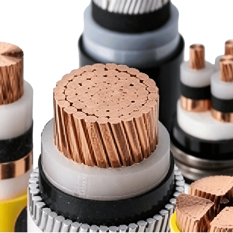
A high voltage power cable is composed of four distinct layers: conductor, conductor screen, insulation, and insulation screen, followed by a metallic shield and outer sheath. Each layer has a defined function. The conductor should have a resistance that meets IEC 60228 class 1 or class 2. The conductor screen and insulation screen smooth out the electric field and prevent partial discharge. The metallic shield serves both as a return path for fault currents and as an electromagnetic shield. The outer sheath can be PVC, PE, or a flame-retardant compound, depending on installation conditions. Pay attention to the conductor material: copper offers lower DC resistance for the same cross-section, while aluminum reduces weight and cost. In a 26/35 kV cable, cross-sections from 50 mm² to 300 mm² are common, and derating factors must be applied when cables are bundled, buried, or installed in hot environments. The semi-conductive screens must be extruded and tightly bonded to the insulation, otherwise voids develop and partial discharge will eventually erode the insulation.
XLPE vs PVC Insulation for Medium and High Voltage
The insulation material determines how much thermal and electrical stress a cable can handle. XLPE (cross-linked polyethylene) is the default choice for medium and high voltage power cables because it can sustain a continuous conductor temperature of 90°C and an emergency temperature up to 130°C. PVC, on the other hand, is usually limited to 70°C continuous temperature. For 0.6/1 kV circuits, PVC remains economical, but for 26/35 kV circuits, XLPE is nearly standard. Table 1 compares the key characteristics. In the field, choosing between these materials is often the first decision that affects the comparison of XLPE and PVC insulation.
| Property | XLPE | PVC | Practical impact |
|---|---|---|---|
| Continuous operating temperature | 90°C | 70°C | Higher current capacity when using XLPE |
| Short-time max conductor temperature | 130°C | 70°C | More overload margin with XLPE |
| Typical voltage class | Up to 35 kV | Usually up to 0.6/1 kV | XLPE is required for medium voltage |
| Moisture resistance | Good | Moderate | XLPE better for buried or damp locations |
| Cost | Higher | Lower | PVC preferred for short low-voltage runs |
Voltage Rating Selection: 8.7/15 kV and 26/35 kV
Voltage ratings are written as U0/U, where U0 is the phase-to-earth voltage and U is the phase-to-phase voltage. For a 26/35 kV cable, U0 is 26 kV and U is 35 kV. In practice, a 26/35 kV XLPE cable is used for power distribution from 35 kV substations, while 8.7/15 kV cables serve industrial indoor feeders and 12/20 kV cables are common in urban distribution networks. Selecting a voltage rating higher than the system's nominal voltage does not necessarily improve reliability; it can increase cost and reduce flexibility. The correct rating is the one that matches the system's maximum operating voltage and the neutral grounding configuration. For example, a system with a 35 kV nominal voltage and an effectively grounded neutral may be served by a 26/35 kV cable, whereas an ungrounded or isolated neutral system may require a higher insulation level. Therefore, always verify the insulation level with the design engineer.
Choosing the Right Conductor Cross-Section
Conductor cross-section selection is a balance of ampacity, voltage drop, and short-circuit capacity. Ampacity is limited by the maximum conductor temperature, which is 90°C for XLPE. A 150 mm² copper conductor in air has an approximate ampacity of 360 A at 90°C, but when buried in soil at 25°C with a thermal resistivity of 1.2 K·m/W, the ampacity can drop below 300 A. Voltage drop must be checked for long runs; a 1% voltage drop at 35 kV usually allows a longer cable length than at 0.6/1 kV. For short circuits, the conductor must not exceed the maximum permissible temperature during the fault clearing time. A standard guide states that copper conductors can withstand a short-circuit current density of about 100 A/mm² for 1 second under XLPE insulation. These calculations determine the minimum cross-section, and procurement should never accept a thinner conductor without a documented thermal calculation.
Where High Voltage Power Cables Are Used
High voltage power cables are found wherever electrical energy must move over distance. Utility grids use 26/35 kV XLPE cables to connect substations and step-down transformers.
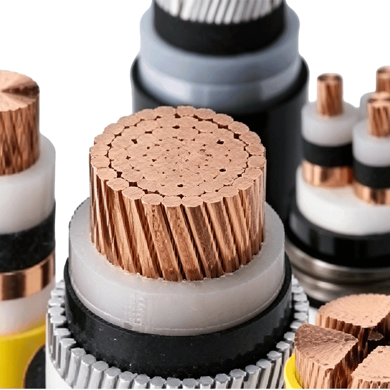 XLPE Insulated Power Cable for Medium and High Voltage DistributionThis cross-linked polyethylene cable suits urban grids, industrial plants, and infrastructure. Its advanced insulation enhances aging and environmental resistance, making it a reliable choice for reliable power transmission over distances.View Product →
Industrial plants install 8.7/15 kV cables to supply large motors and power distribution panels. Rail transit systems use dedicated power cables to feed traction substations.
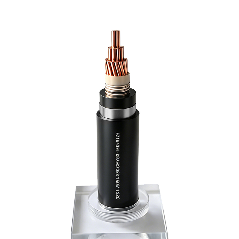 Low-Smoke Halogen-Free Power Cable for Urban Rail TransitEngineered for subway and light rail systems, this 35kV cable offers flame retardancy and protection against termites and rodents. It meets stringent safety requirements for underground and track environments, supporting reliable traction power.View Product →
Renewable energy projects also rely on these cables: a solar farm may use photovoltaic cables to collect direct current from arrays and feed a central inverter.
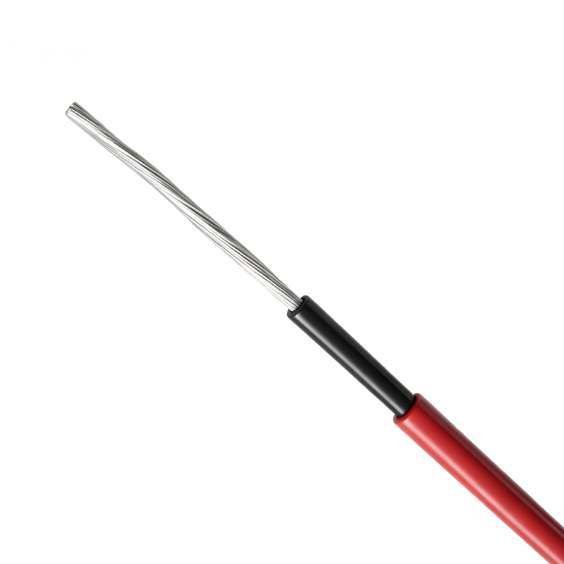 Photovoltaic Cable for Solar Power DC TransmissionDesigned for solar arrays, this cable resists UV, weather, and ozone. Its tinned copper conductor and LSZH insulation ensure stable performance in outdoor conditions, contributing to long-term efficiency of renewable energy systems.View Product →
Quality and Testing Considerations
A reliable high voltage power cable must be tested before leaving the factory. Routine tests include conductor resistance measurement, partial discharge test at the declared voltage, insulation resistance test, and power frequency voltage withstand test. For 26/35 kV cables, the partial discharge test must show no local discharge above the specified limit. In addition, sample tests check dimension, insulation thickness, and mechanical properties. Site acceptance tests typically involve a high voltage direct current test or a resonant alternating current test, depending on the cable system. Insist on receiving the test reports for each reel. Also verify that the factory has the required certification, such as ISO 9001 and product certifications for the intended market.
Practical Buying Considerations
When purchasing high voltage power cables, inventory the following variables: cable length, delivery barrel size, required bending radius, installation depth, and ambient temperature. For direct burial, use cables with a double steel tape armor or a wire armor layer. For cable trays or tunnels, a flame-retardant sheath is needed to reduce fire propagation. The bending radius is often specified as 12 to 15 times the cable outer diameter for XLPE. Dirt, moisture, and mechanical damage are the three most common causes of premature failure in medium voltage cables. Also, compare the thermal derating factors for different routes. A change in installation condition from air to soil can reduce ampacity by 20-30%. Remember that the total cost of ownership includes the cable, the installation, and the cost of failure, so choose a supplier that can provide consistent quality and reliable test documentation.
Choosing a high voltage power cable is an engineering decision based on system voltage, insulation material, conductor size, and installation environment. Start with the specification, then validate the supplier's test capability and track record. A reliable cable manufacturer with ISO 9001 and TÜV certification can provide the necessary documentation and consistency for utility, industry, and renewable projects. Our team has been producing medium and high voltage power cables since 1998, and we welcome your technical questions. Learn more about our manufacturing background.
-
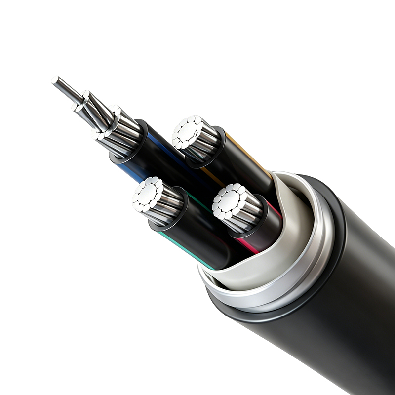
Aluminum Alloy Conductor Plastic Insulated Power Cable (Rated Voltage up to 26/35kV)
-
Power Cable for Subway and Urban Rail Transit (Rated Voltage 35kV)
-
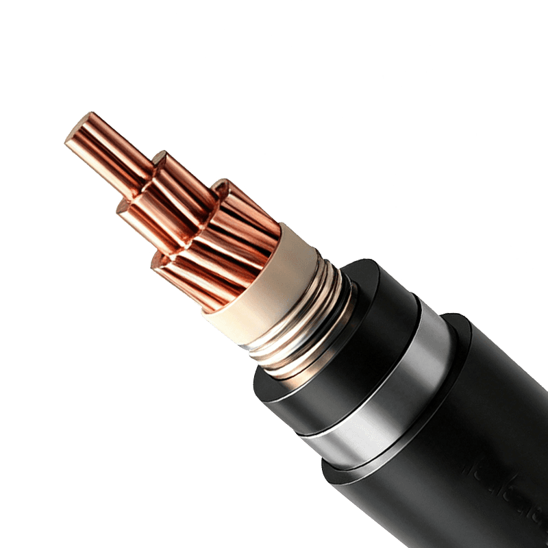
Rated Voltage 3.6/6kV–26/35kV XLPE Insulated Power Cable
-
Rated Voltage 0.6/1kV XLPE Insulated Power Cable
-
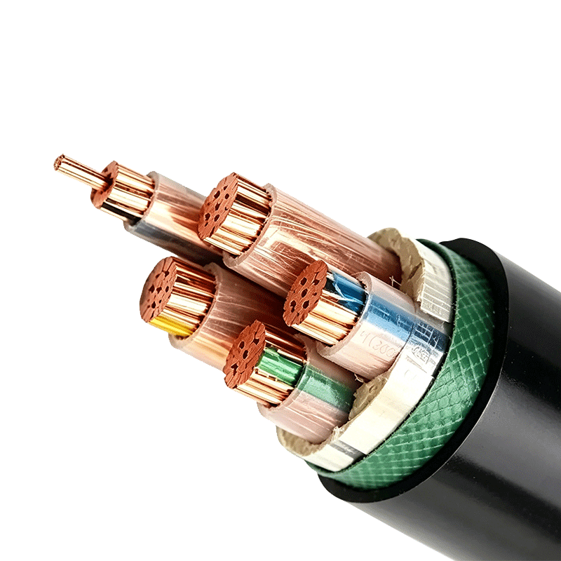
Rated Voltage 0.6/1kV PVC Insulated Power Cable

Copyright © Wuxi Guanghuan Cable Co., Ltd. All Rights Reserved. Power Cables Manufacturer Electrical Wire And Cable Factory

